By this time we know where are our Embedded Systems and what makes them stand out from other systems like Calculators, Desktop Computers, and our Old Television Sets. We have also developed some 6th sense to guess the components of an RTES.
1. Microprocessor
This is the heart of any RTES. The microprocessors used here are different from the general purpose microprocessors like Pentium Sun SPARC etc. They are designed to meet some specific requirements. For example Intel 8048 is a special purpose microprocessor which you will find in the Keyboards of your Desktop computer. It is used to scan the keystrokes and send them in a synchronous manner to your PC. Similarly mobile phones Digital Cameras use special purpose processors for voice and image processing. A washer and dryer may use some other type of processor for Real Time Control and Instrumentation.
2. Memory
The microprocessor and memory must co-exit on the same Power Circuit Board(PCB) or same chip. Compactness, speed and low power consumption are the characteristics required for the memory to be used in an RTES. Therefore, very low power semiconductor memories are used in almost all such devices. For housing the operating system Read Only Memory(ROM) is used. The program or data loaded might exist for considerable duration. It is like changing the setup of your Desktop Computer. Similar user defined setups exist in RTES. For example you may like to change the ring tone of your mobile and keep it for some time. You may like to change the screen color etc. In these cases the memory should be capable of retaining the information even after the power is removed. In other words the memory should be non-volatile and should be easily programmable too. It is achieved by using Flash1 memories.
3. Input Output Devices and Interfaces
Input/Output interfaces are necessary to make the RTES interact with the external world. They could be Visual Display Units such as TFT screens in a mobile phone, touch pad key board, antenna, microphones, speakers etc. These RTES should also have open interfaces to other devices such as Desktop Computers, Local Area Networks (LAN) and other RTES. For example you may like to download your address book into your personal digital assistant (PDA). Or you may like to download some mp3 songs from your favorite internet site into your mp3 player. These input/output devices along with standard software protocols in the RTOS provide the necessary interface to these standards.
4. Software
The RTES is the just the physical body as long as it is not programmed. It is like the human body without life. Whenever you switch on your mobile telephone you might have marked some activities on the screen. Whenever you move from one city to the other you might have noticed the changes on your screen. Or when you are gone for a picnic away from your city you might have marked the no-signal sign. These activities are taken care of by the Real Time Operating System sitting on the non-volatile memory of the RTES.
Besides the above an RTES may have various other components and Application Specific Integrated Circuits (ASIC) for specialized functions such as motor control, modulation, demodulation, CODEC.
information is shared by www.irvs.info
Thursday, August 12, 2010
Wednesday, August 11, 2010
Typical Architecture of Mobile Phone
In general, a cell phone is composed of the following components:
• A Circuit board (Fig. 2.2)
• Antenna
• Microphone
• Speaker
• Liquid crystal display (LCD)
• Keyboard
• Battery

A typical mobile phone handset (Fig. 2.3) should include standard I/O devices (keyboard, LCD), plus a microphone, speaker and antenna for wireless communication. The Digital Signal Processor (DSP) performs the signal processing, and the micro-controller controls the user interface, battery management, call setup etc. The performance specification of the DSP is very crucial since the conversion has to take place in real time. This is why almost all cell phones contain such a special processor dedicated for making digital-to-analog (DA) and analog-to-digital(AD) conversions and real time processing such as modulation and demodulation etc. The Read Only Memory (ROM) and flash memory (Electrically Erasable and Programmable Memory) chips provide storage for the phone’s operating system(RTOS) and various data such as phone numbers, calendars information, games etc.
information provided by www.irvs.info
Tuesday, August 10, 2010
Questions and Answers
Q1 Which of the following is a real time embedded system? Justify your answer
(a) Ceiling Fan
(b) Microwave Oven
(c) Television Set
(d) Desktop Key Board
(e) Digital Camera
Ans:
(b) and (e) are embedded systems
(
(a) Ceiling Fans: These are not programmable.
(b) & (e) obey all definitions of Embedded Systems such as
(i) Working in Real Time (ii) Programmable (iii) A number of systems coexist on a single platform to discharge one function(single functioned)
(c) Television Set: Only a small part of it is programmable. It can work without being programmable. It is not tightly constrained.
(d) Desktop Keyboard: Though it has a processor normally it is not programmable
Q.2 Write five advantages and five disadvantages of embodiment.
Ans:
Five advantages:
1. Smaller Size
2. Smaller Weight
3. Lower Power Consumption
4. Lower Electromagnetic Interference
5. Lower Price
Five disadvantages
1. Lower Mean Time Between Failure
2. Repair and Maintenance is not possible
3. Faster Obsolesce
4. Unmanageable Heat Loss
5. Difficult to Design
Q3. What do you mean by Reactive in Real Time. Cite an example.
Ans:
Many embedded systems must continually react to changes in the system’s environment and must compute certain results in real time without delay. For example, a car’s cruise controller continually monitors and reacts to speed and brake sensors. It must compute acceleration or deceleration amounts repeatedly within a limited time; a delayed computation could result in a failure to maintain control of the car. In contrast a desktop computer system typically focuses on computations, with relatively infrequent (from the computer’s perspective) reactions to input devices. In addition, a delay in those computations, while perhaps inconvenient to the computer user, typically does not result in a system failure.
Monday, August 9, 2010
Definition of Real Time Systems & Embedded System
Definition of Real Time Systems
An operation within a larger dynamic system is called a real-time operation if the combined reaction- and operation-time of a task operating on current events or input, is no longer than the maximum delay allowed, in view of circumstances outside the operation. The task must also occur before the system to be controlled becomes unstable. A real-time operation is not necessarily fast, as slow systems can allow slow real-time operations. This applies for all types of dynamically changing systems. The polar opposite of a real-time operation is a batch job with interactive timesharing falling somewhere in between the two extremes.
Alternately, a system is said to be hard real-time if the correctness of an operation depends not only upon the logical correctness of the operation but also upon the time at which it is performed. An operation performed after the deadline is, by definition, incorrect, and usually has no value. In a soft real-time system the value of an operation declines steadily after the deadline expires.
Embedded System
An embedded system is a special-purpose system in which the computer is completely encapsulated by the device it controls. Unlike a general-purpose computer, such as a personal computer, an embedded system performs pre-defined tasks, usually with very specific requirements. Since the system is dedicated to a specific task, design engineers can optimize it, reducing the size and cost of the product. Embedded systems are often mass-produced, so the cost savings may be multiplied by millions of items.
Handheld computers or PDAs are generally considered embedded devices because of the nature of their hardware design, even though they are more expandable in software terms. This line of definition continues to blur as devices expand.
Saturday, August 7, 2010
Architecture of an Embedded System
ASIC: Application Specific Integrated Circuit: for specific functions like motor control, data modulation etc.
Microcontroller(μC): A family of microprocessors
Real Time Operating System (RTOS): contains all the software for the system control and user interface
Controller Process: The overall control algorithm for the external process. It also provides timing and control for the various units inside the embedded system.
Digital Signal Processor (DSP) a typical family of microprocessors
DSP assembly code: code for DSP stored in program memory
Dual Ported Memory: Data Memory accessible by two processors at the same time
CODEC: Compressor/Decompressor of the data
User Interface Process: The part of the RTOS that runs the software for User Interface activities
Controller Process: The part of the RTOS that runs the software for Timing and Control amongst the various units of the embedded system

The above architecture represents a hypothetical Embedded System (we will see more realistic ones in subsequent examples). More than one microprocessor (2 DSPs and 1 μC) are employed here to carry out different tasks. As we will learn later, the μC is generally meant for simpler and slower jobs such as carrying out a Proportional Integral (PI) control action or interpreting the user commands etc. The DSP is a more heavy duty processor capable of doing real time signal processing and control. Both the DSPs along with their operating systems and codes are independent of each other. They share the same memory without interfering with each other. This kind of memory is known as dual ported memory or two-way post-box memory. The Real Time Operating System (RTOS) controls the timing requirement of all the devices. It executes the over all control algorithm of the process while diverting more complex tasks to the DSPs. It also specifically controls the μC for the necessary user interactivity. The ASICs are specialized units capable of specialized functions such as motor control, voice encoding, modulation/demodulation (MODEM) action etc. They can be digital, analog or mixed signal VLSI circuits. CODECs are generally used for interfacing low power serial Analog-to-Digital Converters (ADCs). The analog signals from the controlled process can be monitored through an ADC interfaced through this CODEC.
Wednesday, August 4, 2010
Common Architecture of Real Time Embedded Systems -part1
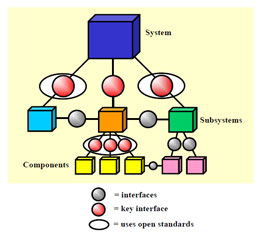
The red and grey spheres in Fig.1.2 represent interface standards. When a system is assembled it starts with some chassis or a single subsystem. Subsequently subsystems are added onto it to make it a complete system.
Let us take the example of a Desktop Computer. Though not an Embedded System it can give us a nice example of assembling a system from its subsystems.
You can start assembling a desktop computer (Fig.1.3) starting with the chassis and then take the SMPS (switched mode power supply), motherboard, followed by hard disk drive, CDROM drive, Graphic Cards, Ethernet Cards etc. Each of these subsystems consists of several components e.g. Application Specific Integrated Circuits (ASICs), microprocessors, Analog as well as Digital VLSI circuits, Miniature Motor and its control electronics, Multilevel Power supply units crystal clock generators, Surface mounted capacitors and resistors etc. In the end you close the chassis and connect Keyboard, Mouse, Speakers, Visual Display Units, Ethernet Cable, Microphone, Camera etc fitting them into certain well-defined sockets.
Common Architecture of Real Time Embedded Systems
Unlike general purpose computers a generic architecture can not be defined for a Real Time Embedded Systems. There are as many architecture as the number of manufacturers. Generalizing them would severely dilute the soul purpose of embodiment and specialization.
However for the sake of our understanding we can discuss some common form of systems at the block diagram level. Any system can hierarchically divided into subsystems. Each sub-system may be further segregated into smaller systems. And each of these smaller systems may consist of some discrete parts. This is called Hardware configuration.
Some of these parts may be programmable and therefore must have some place to keep these programs. In RTES the on-chip or on-board non-volatile memory does keep these programs. These programs are the part of the Real Time Operating System (RTOS) and continually run as long as the gadget is receiving power. A part of the RTOS also executes itself in the stand-by mode while taking a very little power from the battery. This is also called the sleep mode of the system.
Both the hardware and software coexist in a coherent manner. Tasks which can be both carried out by software and hardware affect the design process of the system. For example a multiplication action may be done by hardware or it can be done by software by repeated additions. Hardware based multiplication improves the speed at the cost of increased complexity of the arithmetic logic unit (ALU) of the embedded processor. On the other hand software based multiplication is slower but the ALU is simpler to design. These are some of the conflicting requirements which need to be resolved on the requirements as imposed by the overall system. This is known as Hardware-Software Codesign or simply Codesign.
Let us treat both the hardware and the imbibed software in the same spirit and treat them as systems or subsystems. Later on we shall know where to put them together and how. Thus we can now draw a hierarchical block diagram representation of the whole system as follows:
Version
Subscribe to:
Posts (Atom)